Week 1
Week 1 consisted mostly of planning and assignment designation. Each group member was assigned a part of the project to work on; in this case, each member was assigned to either gear design or the design of the main housing. The group also discussed the different materials that would be used for each component of the turbine. A large part of the turbine's overall efficiency is the number of blades that will be used, so the group discussed that along with what material they would be made of. Another large topic of discussion was the overall budget that the group would be working with. Some minor decisions were made about which components would be bought and which materials would be the most cost efficient and functional.
Week 2
Week 2 involved much more decision making than Week 1. The materials for certain parts were designated, a timeline was estimated for the general duration of each component of the project, and a budget was set in place. The group decided that the gears would be made from Drexel's Rapid Prototyping machine to save costs and time. It was also decided that metal shafts would be purchased to increase the rigidity and durability of the final design. A specially threaded shaft will be designed for the automatic transmission. An automatic transmission, though more difficult to design, will increase the efficiency of the overall design. The housing will be constructed of wood, and the blades will be made from PVC pipe. Among other items to be purchased are a steel base, superglue, and bolts.
UPDATE: Based upon ease of use and durability, a manual transmission was selected instead of an automatic transmission.
Week 3
For Week 3, the group made progress on the design of the gearing and overall transmission. The spacing between gears was measured out on the primary and secondary shafts, and other adjustments to the design were made in Creo Parametric.
As far as acquiring necessary materials, a lighter, polypropylene composite was obtained instead of the planned PVC pipe for the construction of the blades. Using such a material will increase the blades' ability to turn and decrease the amount of force required from the wind to turn them.
The blades of the wind turbine will follow a similar design using the plastic composite pipe.
 |
| Harris, Kevin. "PVC Wind Turbine blade construction". Drawing. TheKevDog.com 10 Apr. 2013. <www.thekevdog.com>. |
Week 4
Progress was made in the development of the gears that would be used. The gears that were designed were .375, .5, 1, 1.5, and 1.625 inch gears. It was decided that each gear would be mounted to a hexagonal shaft to improve the torsional durability of the overall design.
 |
| Walton, Nate. ".375 inch gear". Photo. 23 Apr 2013. |
 |
| Walton, Nate. ".5 inch gear". Photo. 23 Apr 2013. |
|
|
 |
| Walton, Nate. "1 inch gear". Photo. 23 Apr 2013. |
 |
| Walton, Nate. "1.5 inch gear". Photo. 23 Apr 2013. |
 |
| Walton, Nate. "1.625 inch gear". Photo. 23 Apr 2013. |
Week 5
Significant work was made in the development of the turbine blades. From the drawing outlined in Week 3, the polypropylene pipe was measured into 3 segments of 150, 150 and 60 degrees.
 |
| Simpson, David. "Original Polypropylene Pipe". Photo. 27 Apr 2013. |
 |
| Simpson, David. "Pipe Measurements". Photo. 27 Apr 2013. |
|
After the proper measurements were made and drawn on the pipe, three cuts were made to divide the pipe into three sections of 150, 150, and 60 degrees.
 |
| Simpson, David. "Individual cuts". Photo. 27 Apr 2013. |
Then each 150 degree section of pipe was cut down to a length of 5 inches, which was the length that would provide the best proportions for harnessing wind energy.
 |
| Simpson, David. "5inch 150 degree cuts". Photo. 27 Apr 2013. |
After the 5 inch pieces were made, they were then cut diagonally to create a more efficient blade shape.
 |
| Simpson, David. "Blade Cross-sections". Photo. 27 Apr 2013 | . |
Week 6
In Week 6, the group was able to complete a design for the layout of the housing, including the shafts and gear placement. Based on the design, there will be three different gears that will be switched to manually.
 |
| Walton, Nate. "Primary Shaft". Photo. 5 May 2013. |
 |
| Walton, Nate. "Secondary Shaft". Photo. 5 May 2013. |
 |
| Walton, Nate. "Short Shaft". Photo. 5 May 2013. |
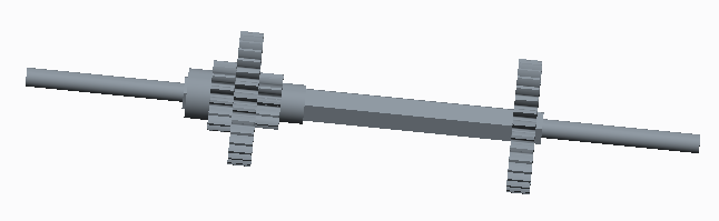
In Creo Parametric, the gears were assembled onto each shaft.
 |
| Walton, Nate. "Assembled Primary Shaft". Photo. 5 May 2013. |
 |
| Walton, Nate. "Assembled Secondary Shaft". Photo. 5 May 2013. |
 |
| Walton, Nate. "Short Chain 1". Photo. 5 May 2013. |
 |
| Walton, Nate. "Short Chain 2". Photo. 5 May 2013. |
 |
| Walton, Nate. "Final Short Chain". Photo. 5 May 2013. |
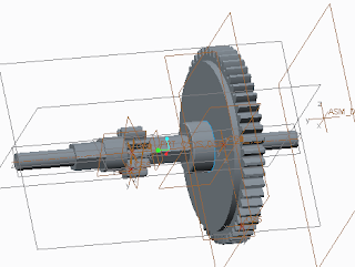
From the gear assembly and housing design, each part of the full gearbox was assembled in Creo Parametric.
 |
| Walton, Nate. "Basic Housing". Photo. 5 May 2013. |
|
 |
| Walton, Nate. "Assembled Gearbox". Photo. 5 May 2013. |
Among other progress made in Week 6, more materials were ordered. The metal for shafts was ordered, adhesives to bind the metals, and washers to connect the blades and act as a rotor.
Week 7
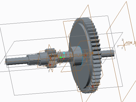
Significant progress was made in Week 7. The hexagonal shafts were cut down in the machine shop and shaped using a lathe. Also, updates were made to the gearing layout and the construction of the overall transmission. A gear was also made to attach from the end of the transmission to the electrical generator.
 |
| Walton, Nate. "Redesigned Primary Shaft". Photo. 16 May 2013. |
 |
| Walton, Nate. "Redesigned Shaft". Photo. 16 May 2013. |
 |
| Walton, Nate. "Shaft Redesign". Photo. 16 May 2013. |
 |
| Walton, Nate. "Gearbox With Updated Shafts". Photo. 16 May 2013. |
 |
| Walton, Nate. "Generator Attachment". Photo. 16 May 2013. |
 |
| Dolan, Thomas. "Printed Gears". Photo. 23 May 2013. |
The shafts were constructed from metal, hexagonal rods. The rods needed to be altered to have easy installation in the gearbox as well as smooth rotation.
Below are a few pictures of the rods being cut, lathed, and then the final products.
 |
| Sousa, Kevin. "Shaft Rod Cutting". Photo. 13 May 2013. |
 |
| Sousa, Kevin. "Lathe". Photo. 13 May 2013. |
 |
| Sousa, Kevin. "Finished Shafts". Photo. 13 May 2013. |
On the "Tutorials" page, there is a video shows the lathing process.
Week 8
Throughout Week 8, significant progress was made in the assembly of the gears to the shafts, and also the shafts to the housing. The housing was constructed of wood, and each subsection was properly measured to support its designated shaft. The shafts were originally hexagonal, but the ends were machined into a cylindrical shape so they could easily fit into the drilled holes of each subsection.
 |
| Simpson, David. "Gearbox assembly". Photo. 23 May 2013. |
 |
| Simpson, David. "Progress on Gearbox Assembly". Photo. 23 May 2013. |
Week 9
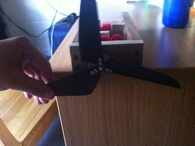
In Week 9, the finishing touches were made to the gearbox assembly, and the construction of the rotor went underway. The completed polypropylene blades were attached to a washer using two nuts. The completed rotor was then fastened to the main shaft where it could then undergo rotation.
 |
| Simpson, David. "Completed Rotor". Photo. 29 May 2013. |
|
|
 |
| Simpson, David. "Completed Rotor Blade Attachment". Photo. 29 May 2013. |
 |
| Simpson, David. "Rotor Attachment". Photo. 29 May 2013. |
UPDATE: Later in Week 9, the assembly of the gearbox onto the housing stand took place. For weight and stability, a block of steel was placed in the legs of the would stand just above the bottom platform.
 |
| Walton, Nate. "Platform and Stand Assembly". Photo. 30 May 2013. |
Week 10
In Week 10, the final touches were made to the turbine after initial testing. Each gear had an incredibly high gear ratio, so only first gear worked in the wind tunnel. The force that the wind tunnel generated was not enough to turn the blades in both second and third gear. To adjust this, shafts were taken out at the end of the transmission to reduce the amount of resistance that was keeping the rotor from spinning.
Here is a video displaying the final testing after the adjustments were made.


No comments:
Post a Comment